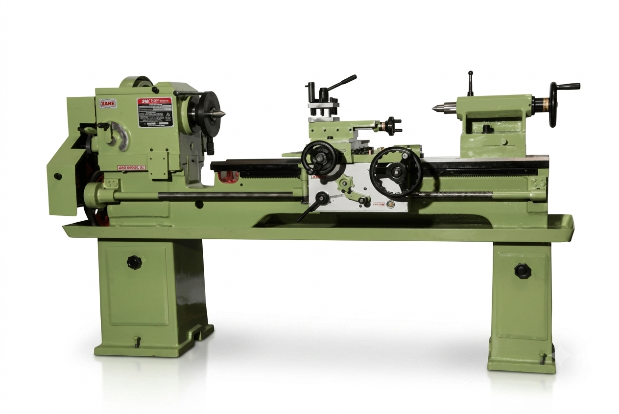
Lathe Machine Training
Model: AI-108
Category: Physics
Subcategory: Advance Physics
Description
Practical Training on Centre Lathe Machine
The Lathe Machine Training System is designed to provide students, trainees, apprentices, and technical professionals with practical knowledge of conventional lathe machine operation. The training covers the fundamentals of turning, facing, drilling, threading, knurling, taper turning, boring, and other essential machining operations.
A centre lathe is one of the most important machines used in mechanical workshops because it can perform a wide range of operations by rotating the workpiece against a cutting tool. The training enables learners to understand machine construction, work holding, cutting tools, operating procedures, measurement, machining parameters, and safe workshop practices.
Training Objectives
After completing the training, trainees will be able to:
Identify the major parts and functions of a lathe machine.
Understand the working principle of a centre lathe.
Select suitable cutting tools for different machining operations.
Mount and align workpieces using 3-jaw and 4-jaw chucks.
Set cutting speed, feed, and depth of cut.
Perform facing and straight turning operations.
Perform step turning and shoulder turning.
Carry out drilling and boring operations.
Perform external and internal threading.
Perform knurling operations.
Understand and perform basic taper turning.
Use measuring instruments such as vernier calipers and micrometers.
Read basic engineering drawings and machining dimensions.
Calculate machining parameters and thread-related settings.
Follow proper machine-operation and workshop safety procedures.
Major Parts Covered
The training provides detailed practical understanding of:
Machine Bed
Headstock
Main Spindle
Chuck
Tailstock
Carriage
Saddle
Cross Slide
Compound Rest
Tool Post
Apron
Lead Screw
Feed Rod
Change Gear / Gearbox
Steady Rest
Follow Rest
Tailstock Quill
Centre and Work Holding Devices
Practical Operations
1. Facing
Removal of material from the end face of a workpiece to obtain a flat and accurate surface.
2. Straight Turning
Reduction of the external diameter of a cylindrical workpiece to the required dimension.
3. Step Turning
Machining a workpiece to two or more different diameters according to the drawing.
4. Taper Turning
Producing a conical surface where the diameter gradually changes along the length of the component.
5. Thread Cutting
Producing external or internal threads using the lead screw and appropriate gear/feed settings.
6. Drilling
Producing a hole in the workpiece using a drill mounted in the tailstock.
7. Boring
Enlarging or finishing an existing hole to obtain the required diameter and accuracy.
8. Knurling
Producing a regular patterned surface on a cylindrical component for improved grip or appearance.
9. Chamfering
Removing sharp edges from the workpiece to produce a safe and finished edge.
10. Parting-Off
Separating a finished component from the parent material using a parting tool.
Standard Accessories
The training setup can be supplied with suitable accessories such as:
3-Jaw Self-Centring Chuck
4-Jaw Independent Chuck
Face Plate
Driving Plate
Dead Centre
Revolving Centre
Drill Chuck
Tool Post
Turning Tools
Facing Tool
Parting Tool
Threading Tool
Boring Tool
Knurling Tool
Steady Rest
Follow Rest
Change Gears
Chuck Key
Tool Post Wrench
Spanners and Machine Tools
Measurement & Inspection Training
Practical measurement is an essential part of lathe-machine training. Trainees can learn to use:
Steel Rule
Vernier Caliper
Outside Micrometer
Inside Micrometer
Dial Indicator
Depth Gauge
Thread Pitch Gauge
Vernier Height Gauge
Try Square
Students are trained to compare the machined component with the dimensions specified in the engineering drawing and identify dimensional errors.
Cutting Parameters Covered
The training introduces the relationship between:
Cutting Speed → Spindle Speed → Feed → Depth of Cut → Material Removal Rate
Trainees learn how machining parameters influence surface finish, tool life, dimensional accuracy, machining time, and productivity.
Important parameters include:
Cutting Speed
Spindle RPM
Feed Rate
Depth of Cut
Workpiece Diameter
Tool Geometry
Material Type
Coolant/Lubrication
Safety Training
Machine safety is an integral part of the programme. Trainees are instructed in:
Proper machine start-up and shutdown procedures.
Correct workpiece clamping.
Safe chuck operation.
Proper tool setting and tightening.
Removal of chuck keys before starting the machine.
Correct use of personal protective equipment.
Safe handling of cutting tools and workpieces.
Safe removal of metal chips.
Emergency-stop procedures.
Proper housekeeping around the machine.
Recommended Training Projects
Practical projects may include:
Project 1 – Basic Turning Job
Facing, centre drilling and straight turning of a cylindrical workpiece.
Project 2 – Step Turning Job
Production of multiple diameters according to an engineering drawing.
Project 3 – Threaded Component
External thread cutting using the appropriate lead-screw and feed settings.
Project 4 – Taper Component
Production of a basic tapered component using a suitable taper-turning method.
Project 5 – Complete Workshop Component
A multi-operation job involving facing, turning, drilling, boring, chamfering, threading and parting-off.
Applications
Lathe machine training is suitable for:
Industrial Training Institutes (ITIs)
Polytechnic Colleges
Engineering Colleges
Vocational Training Centres
Skill Development Centres
Mechanical Engineering Laboratories
Industrial Training Workshops
Apprentice Training Centres
Technical Demonstration Laboratories
Why Lathe Machine Training Matters
A trainee who understands only the theory of machining is not fully prepared for a real workshop. Effective lathe training combines machine operation, engineering drawings, tooling, measurement, machining calculations, practical component production, and safety.
The objective is not simply to teach students how to operate the handles of a lathe. It is to develop the ability to select the correct process, set the machine correctly, produce the required component, measure the result, and identify machining problems.
Key Learning Outcome
Learn → Set → Machine → Measure → Inspect → Improve
This practical approach helps learners build the foundation required for conventional machining and prepares them for more advanced manufacturing technologies, including CNC turning.
Technical Specifications
The following specifications represent a typical educational/industrial centre lathe configuration. Exact specifications can be customized according to the required machine model and training application. Standard lathe specifications commonly include swing over bed, swing over cross slide, distance between centres, spindle bore, spindle speeds, motor power, bed dimensions, and lead-screw specifications.
| Parameter | Technical Specification |
|---|---|
| Machine Type | Centre / Engine Lathe |
| Application | Training, Education & Workshop Practice |
| Swing Over Bed | Approx. 350 mm or higher |
| Swing Over Cross Slide | Approx. 190 mm or higher |
| Distance Between Centres | Approx. 750–800 mm |
| Maximum Turning Length | Approx. 700–750 mm |
| Bed Width | Approx. 240 mm or higher |
| Spindle Bore | Approx. 35 mm or higher |
| Spindle Taper | MT-5 |
| Chuck | 3-Jaw Self-Centring Chuck |
| Additional Chuck | 4-Jaw Independent Chuck |
| Spindle Speed | Multiple speeds; configuration dependent |
| Typical Speed Range | Approx. 50–2000 RPM, depending on model |
| Cross Slide Travel | Approx. 175–190 mm |
| Compound Slide | Approx. 100 mm or higher |
| Tool Post | Quick-Change / 4-Way Tool Post |
| Tailstock | Adjustable Tailstock with Morse Taper |
| Lead Screw | Provided for threading operations |
| Feed Mechanism | Longitudinal and cross feed |
| Threading | Metric / Inch, depending on gearbox configuration |
| Drive System | Geared / Belt-driven configuration as specified |
| Motor | As per machine model and application |
| Machine Construction | Rigid Cast-Iron Bed |
| Work Holding | 3-Jaw, 4-Jaw, Faceplate and Centres |
| Training Level | Basic to Advanced Workshop Practice |
For reference, educational centre-lathe specifications published by technical institutions include configurations around 350 mm swing over bed, 190 mm swing over cross slide, 750–800 mm distance between centres and 35 mm minimum spindle bore.